Abstract— In this contribution we introduce a simple radio
frequency (RF) tag that can be configured to exhibit direction dependent
modulation properties. The tag consists of a two-by-two array of pin diode
loaded dipole elements that can be controlled by an external signal to modulate
the RF scattering characteristics of the tag. The design of the tag allows for multilevel
in-phase and quadrature modulation schemes to be implemented. It will also be shown
that the form of the modulation generated by the tag is direction dependent and
that this property can be exploited to provide an additional degree of system
security.
Keywords-PSS; Secure Communication; Directional Phase
Modulation; RFID; Antennas
The concept of directional modulation
was recently proposed as a means for enhancing the security of wireless data
transmission [1]. The idea was originally applied to a transmitting array
antenna and involves imparting baseband data on to the transmitted signal by directly
modulating the elements of the array. If
this process is performed correctly, the form of the modulated signal
transmitted by the antenna changes with observation angle. So, for example, the
antenna may configured to radiated a 16 level QAM signal on boresight, but at
angles away from boresight the modulation scheme will be corrupted. This
property has been proposed as means of enhancing the security of data
transmission as it makes interception and decoding by an eavesdropper a
difficult task. Recently we have
investigated applying directional modulation to the scattering properties of an
RFID tag. The general concept of directional modulation may be explained by
referring to Figure 1 which shows an RF tag which is illuminated at boresight
by a cw RF signal. The tag is assumed to be configured to impart symmetrical
QPSK modulation on to directly reflected signals (boresight direction). At
angles away from boresight however, the form of the constellation diagram
changes and it no longer exhibits the original symmetrical form of QPSK. Indeed
in can be shown that in certain situations the distortion of the original
constellation diagram with angle can result in the complete elimination of
certain constellation points making successful detection and demodulation an almost
impossible task [2].
The RF tag we are investigating is
based on the concept of an active phase modulating surface or phase-switched
screen (PSS) and consists of a two-by-two array of pin diode loaded dipole
elements placed above a conducting ground plane. By applying a bias voltage to
the pin diodes, the dipoles can be switched between resonant and non-resonant
impedances. Hence, to a first order approximation, the diodes may be considered
opaque (when resonant) or transparent (when non-resonant) in which case the primary
scattering will occur from either the dipole surface or the conducting
back-plane. To model the basic scattering behaviour of the tag we introduce a
very simplified analytic model in which the tag is represented by two four
element arrays of isotropic scattering sources as show in Figure 2. The elements
of the upper array represent scattering from the resonant dipoles and those of the
lower array represent scattering from the ground plane when the dipoles are
non-resonant. For the results presented
here, both arrays are assumed to have x-y element separation distances of a
quarter of a wavelength at the illumination frequency. In addition, the
vertical (z) spacing between the upper and lower arrays is also a quarter of wavelength.
For this configuration scattering can
occur either from an upper element or the one directly below it – but not from
both simultaneously - so that we have a total of 16 possible scattering state
combinations. However for boresight scattering, symmetry dictates that nine of
these combinations produce identical solutions and so only five distinct
scattering states exist. These points are shown in the constellation diagram of
Figure 3 and exhibit the characteristics of multi-level BPSK modulation. Also shown
in Figure 3 is the constellation diagram produced at a scattering angle of 450
and generated by the same set of tag modulation parameters that generated the 5
boresight points. From the constellation diagram it is clear that the
modulation function has changed significantly with scattering angle, as the
form of the modulation pattern at 450 has the characteristics of a
multi-level QAM scheme. This property of
angle dependent modulation can be exploited to increase the security of data
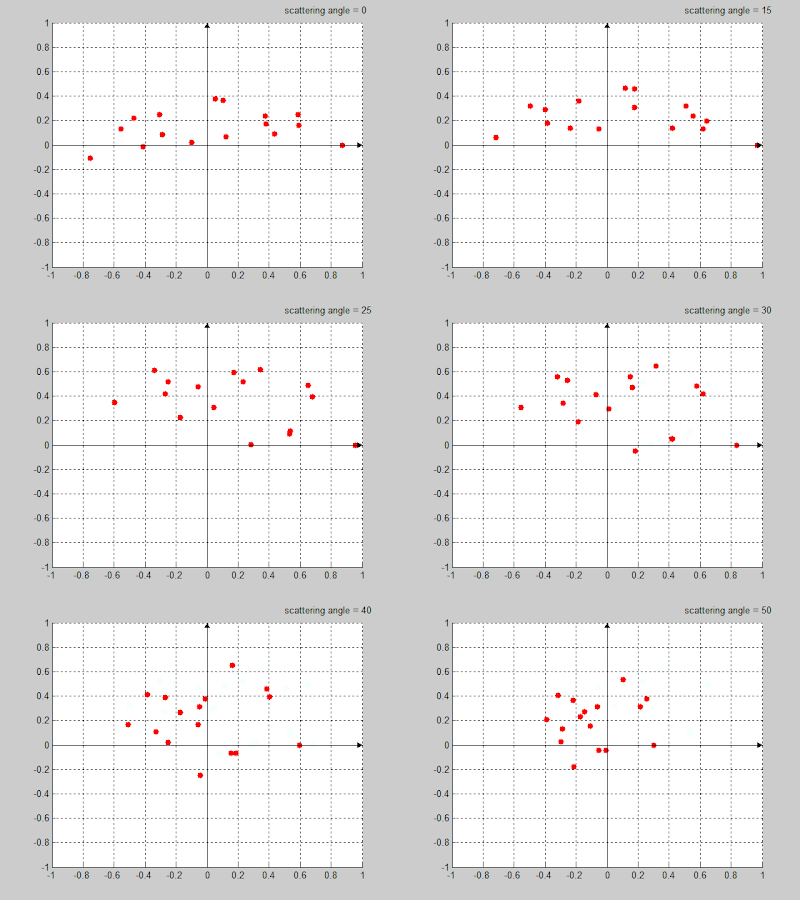
transmission and this will be examined and reported in the final paper. Simulated results are reported in Figure 4. The measured data from a prototype experimental system will be shown later.
Fig. 5 shows a animation of both ideal and measured constellation digram changing w.r.t. the scattering angle. It is very clear that the scattered signals away from boresight are identical to boresight. Thus it is hard for a listener at other directions to demodulate the original information even with the right demodulation scheme.
A simple short-distance demodulation scheme are employed to test the reliability of the system. Fig. 6 shows the symbol error rate (SER) with respect to scattering angles. SER stays very low at boresight and near angle and rise up from 30 degree. The beam of the operating angle is about 50 degree.
Figure 3. Ideal constellation diagram
Figure 4. Simulated constellation diagram
Figure 5. Animation of Ideal and Simulated constellation diagram w.r.t. scattering angle
Figure 6. demodulation error rate w.r.t sacttering angle
 |
| Add caption |
[1] M. Daly and J. Bernhard, “Directional modulation technique for phased arrays,” IEEE Trans. on Antenna and Propagation, vol. 57, pp. 2633–2640, Sep. 2009
[2] H.
Shi and A. Tennant, "Directional dependent antenna modulation using a two
element array", Proc. of the 5th EUCAP, pp. 812-815, Apr. 2011


